Abstract:
As a Network Engineer in a medium sized corporation, I’ve found a need for an Out Of Band Management solution for our Network equipment. The problem is that prepackaged professional solutions are very expensive. Since they are only needed every so often, justifying the financial expense can be difficult. Having an interest in Open Source, Linux and Raspberry Pi, I figured I could develop something much more budget friendly and just as useful. This document outlines the results of this work.
Background:
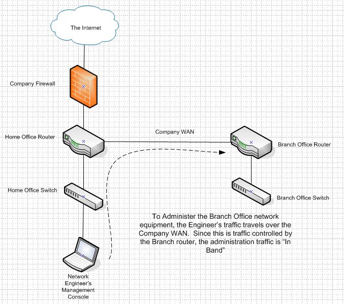
When Network Engineers need to make changes to Routers, Switches, firewalls and other equipment that make up the modern corporate network infrastructure, usually the engineer will connect to an IP address of the target equipment using a Web Browser for GUI based administration or Telnet/SSH for command line administration. When connecting in this fashion, the engineer is said to be connecting “In-Band” because the management traffic is using the same bandwidth that the target equipment is controlling.
 For most scenarios, In-Band management is sufficient. However, there are times when the target equipment is having a problem that prevents In-Band connectivity or the change the Engineer needs to make is a multi-step change where one step will break the connectivity before a subsequent step can be made to re-establish the connectivity. In these cases, an Out-Of-Band method to connect is necessary.

Traditionally, Network engineers would place phone lines in key locations where Out-Of-Band management is anticipated to be needed and then use a modem to dial in to another modem that is connected to the console port of the remote equipment. This solution works well, but has the drawback of requiring phone lines in a lot of locations at considerable expense.
 One alternative to the traditional Phone line for OoBM (Out of Band Management) is a Product by OpenGear called the ACM5000. The ACM5000 can allow for OoBM management over a Cellular connection. This adds flexibility that telephone lines can’t provide as the Out of Band connectivity can be brought to the equipment requiring it as needed. The downside of the OpenGear solution is that the equipment can be costly and outside the scope of a Small IT department Budget.
This brings us to the subject of this paper, using Open Source tools that are freely available with low cost hardware to build our own OoBM Device that utilizes the cellular network. The initial hardware investment for this Open Source OoBM Device was $118.53 +S&H at the time of this writing. This is significantly less than the $820 for a 4 port OpenGear ACM5000. The only additional costs are the recurring fees for the Cellular data service and any of the optional testing hardware and software you may not have on hand listed in the BoM. Lastly, being Linux based there are other features you can add, like local TFTP/FTP/SFTP servers or an Iperf server for example, each of which extending your ROI on the nominal investment.
 Disclaimer:
As you read this it will become obvious that this device can be used for other “Phone Home” services that exist behind firewalls, some of which could be considered nefarious. In our case we are paying the Cellular Provider for internet connectivity and only using internet connectivity to access our own equipment. So we are connecting within the service provider’s terms of use. However, use of a device of this type on corporate networks or other networks without permission of the network owner could be construed as unauthorized access and may be against the law in your jurisdiction. I suggest you use good judgment and research the usage policies of the networks you intend on using this device on. When appropriate you should get written permission.
Getting Started:
The biggest issue you are likely to face is picking the right modem for your service provider and finding the correct PPP settings to use. This document is being written based on AT&T as that is our company’s service provider.
The instructions contained within this document assume you already have a Raspberry Pi capable of booting to a fully updated Raspian command line and that you have some basic understanding of networking and the Linux command line. Instructions for installing the OS, as well as the OS itself can be found here: http://www.raspberrypi.org/downloads/ Additionally, I prefer VIM as a text editor and have installed it, the commands listed below all reference VIM for files to be edited. Feel free to substitute your favorite text editor.
For the initial stages of the installation, as we install software on the device, an internet connection is required. After the PPP configuration is established, the Cellular PPP connection can be used for this. However, due to data plans which may cost you for the usage and the lower performance of the cellular network, it’s advisable to have internet access through the Pi’s Ethernet port until the configuration is complete.
One thing I found regarding the Raspian image was that the default image uses a UK keyboard layout. If you’re doing this from the US and find that the Pipe Key (|) gives you a Tilde(~), you’ll need to change from the default UK Keyboard Layout to the keyboard of your choice.
- Sudo dpkg-reconfigure keyboard-configuration
- Follow the on screen prompts for me choosing Generic 102 Key Keyboard with US layout was necessary.
- Reboot the Pi: sudo shutdown -r now
Lastly quite a bit of what I’ve put together here is an amalgamation of my scripting, troubleshooting and more importantly the work of previous individuals who were so kind as to post their work to the Internet. I will try to give credit when I can.
Conventions:
Italicized Bold Text is a command or text to input in the Pi
Italicized Non-Bold Text is expected results of a command
Hardware Bill of Materials (BoM) you’ll need to operate the device:
- Raspberry Pi
- I’m using a Model B, but an A or B+ should work fine
- An SD Card for your Pi Large enough to support the Raspberry Pi image of your choice.
- I’m using a 8 Gig Sandisk Card and Raspbian Wheezy Distro
- A Powered USB Hub
- This will power the Pi and the Cellular Modem.
- The Pi’s internal USB Hub does not provide enough power for the Cellular modem causing it to intermittently crash, the powered Hub resolves this issue.
- I’m using a Belkin F5U404-BLK for its small size and inexpensive price.
- TrendNet TU-S9 Prolific USB-Serial Adapter Cable
- A Serial cable compatible with the equipment from your network manufacturer
- I’m using a Cisco Rollover cable.
- An UNLOCKED Cellular Modem compatible with your cellular provider
- I’m using a Huawei E398 unlocked Quad Band modem, branded for AT&T
- For AT&T, an AT&T SIM Card with a DataConnect Data Plan associated.
- It’s important that you make sure the Cellular Modem works on the same frequencies for LTE that are used by your provider.
- A “Home” Server running the Linux Distribution of your choice.
- This server needs to be accessible from the internet via TCP/22
- The server needs to have the SSH Daemon installed.
- This server can be Virtual at no hardware cost.
Additional hardware for setting up and testing the Pi, this equipment won’t be required afterwards:
- A USB Keyboard
- A HDMI Monitor (or HDMI-VGA Adapter)
- Cross over cable (used for post deployment re-configuration)
- A Laptop with WiFi and Ethernet for remote administration on the Pi.
- PuTTY or your favorite Terminal Emulation Software
Configuring the Pi:
There are four primary components used for the OoBM device. The first is the Cellular connection, which in our case will be initiated via PPP to AT&T’s network, and will provide us Internet connectivity. The second is a Reverse SSH Tunnel that the Pi will initiate to our home server since it will get a private IP address and be behind a firewall on the Cellular network. The third is the Console connection to the network equipment and the last is a couple of scripts to start and maintain the cellular connection and SSH session upon booting the device.
Part 1 Configuring the Modem and PPP:
The first phase of configuration involves getting the modem hardware to work. By default the modem mounts as a mass storage device. We have to configure, using modeswitch, the Raspberry Pi to see the modem as a modem and not a thumb drive. I received a lot of help with the modem configuration from John C’s article: http://www.jonshobbies.com/installing-a-hawei-e353-cell-modem-on-raspberry-pi-tmobile.html. I would advise you look at his research. He goes in to further detail than I and his info is helpful for troubleshooting.
- Insert the SIM Card in to the Huawei Modem; connect the modem to the Powered USB Hub and the Hub to the Pi.
- Power up the Pi
- Install usb-modeswitch to that we can configure the Pi to see the modem as a modem and not just a mass storage device: sudo apt-get install usb-modeswitch
- Issue the lsusb and you should see the modem as follows:
- Bus 001 Device 007: ID 12d1:1446 Huawei Technologies Co., Ltd. E398 LTE/UMTS/GSM Modem/Networkcard
- 1446 denotes the card is running in mass storage mode
- Change directories to the location of the usb modeswitch files files: cd /usr/share/usb_modeswitch/
- Extract the file we need from the modeswitch configuration pack: sudo tar -xvf configPack.tar.gz 12d1:1446
- Copy the correct modeswitch file to the configuration: sudo cp 12d1\:1446 /etc/usb_modeswitch.d/
- Then edit the file you just copied: sudo vim /etc/usb_modeswitch.d/12d1\:1446
- Add the following lines directly above the TargetVendor entry in the/etc/usb_modeswitch.d/12d1\:1446 file:
- DefaultVendor= 0x12d1
- DefaultProduct= 0x1446
- Now reboot the Pi: sudo shutdown -r now
- After rebooting issuing the lsusb command should now show the Modem in modem mode 1506:
- Bus 001 Device 007: ID 12d1:1506 Huawei Technologies Co., Ltd. E398 LTE/UMTS/GSM Modem/Networkcard
- Issue the command: dmesg | grep ttyUSB
- [ 5.420339] usb 1-1.2.4: GSM modem (1-port) converter now attached to ttyUSB0
- [ 5.495856] usb 1-1.2.4: GSM modem (1-port) converter now attached to ttyUSB1
- [ 5.709823] usb 1-1.2.4: GSM modem (1-port) converter now attached to ttyUSB2
- Depending your hardware configuration (E.G. If you’ve already connected the USB-Serial adapter) the ttyUSB numbers may be different. The modem will always capture 3 consecutive numbers and the lowest number is always the port used to communicate with the modem.
- Install screen: sudo apt-get install screen
- Test the modem hardware works by issuing the command: screen /dev/ttyUSB0 where 0 matches the lowest number ttyUSB associated with the GSM Modem.
- Once in Screen Enter AT and hit enter.
- OK should be returned by the modem.
- Exit screen: Control+a then d
- Exit Screen and reboot the Pi to release the ttyUSB port: sudo shutdown -r now
Configure PPP:
Getting this to work was the most difficult since most vendors don’t provide connectivity information from a Linux command line. If you’re using AT&T like myself, you’re about to benefit from my research. If you are using another Cellular provider, expect that you’ll have to do additional research, troubleshooting and trial and error. The connection scripts for AT&T come from their support article : http://www.att.com/esupport/article.jsp?sid=36059&cv=820#fbid=vo6pnlgsjWS
It’s important to note that you’ll need to have the appropriate Data Plan with your vendor. For AT&T, this is a DataConnect Plan that will support Cellular Dongles.
Also important, in steps 5 and 6 below, we are configuring the AT&T APN to connect to. AT&T has at least 4 APNs this was the only one that I could get to work. The others reject the connection, usually with an invalid SIM card error. You’ll need to do the research for your vendor to find out the correct plan and APN combination. One way I found the correct information was to install the Dongle on a Windows computer and then use the Windows Utility provided by the Cellular Provider. Within this utility I was able to find the correct APN settings required to complete this configuration.
- Install the PPP daemon: sudo apt-get install ppp
- Create three new files in /etc/ppp/peers/
- sudo touch /etc/ppp/peers/gprs-connect-chat
- sudo touch /etc/ppp/peers/gprs-disconnect-chat
- sudo touch /etc/ppp/peers/gprs
- Edit the gprs-connect-chat file: sudo vim /etc/ppp/peers/gprs-connect-chat
- Copy the contents of the connect chat script from http://www.att.com/esupport/article.jsp?sid=36059&cv=820#fbid=vo6pnlgsjWS
- Comment out the line: #OK AT+CGDCONT=1,”IP”,”isp.cingular” or “Broadband”
- Add a new line: OK AT+CGDCONT=1,”IP”,”broadband”
- Save and close the connect chat script.
- Edit the gprs-connect-chat file: sudo vim /etc/ppp/peers/gprs-disconnect-chat
- Copy the contents of the connect chat script from http://www.att.com/esupport/article.jsp?sid=36059&cv=820#fbid=vo6pnlgsjWS
- Save and close the disconnect Chat Script
- Edit the gprs file: sudo vim /etc/ppp/peers/gprs
- Copy the contents of the connect chat script from http://www.att.com/esupport/article.jsp?sid=36059&cv=820#fbid=vo6pnlgsjWS
- Comment out the line: #nodetach to make the connection start silently
- Comment out the line: #debug to make the connection start silently
- Comment out the line: #/dev/modem
- Uncomment the line: /dev/ttyUSB0
- Change the number of the ttyUSB port if necessary as per the results of the dmesg | grep ttyUSB
- Change the maxfail 99 to maxfail 1
- Uncomment: ipcp-accept-local for DHCP from the provider
- Add the line: ipcp-accept-remote for DHCP from the provider
- Save and close the file.
- Edit the PAP secrets file: sudo vim /etc/ppp/pap-secrets
- Add the line: WAP@CINGULARGPRS.COM * CINGULAR1
Save and close the file. - Edit the PAP secrets file: sudo vim /etc/ppp/chap-secrets
- Add the line: WAP@CINGULARGPRS.COM gprs CINGULAR1 *
- Save and close the file.
- Edit the ppp Global Configuration: sudo vim /etc/ppp/options
- Comment out the #auth option
Configure IP Networking and the PPP interface:
We’re going to setup our IP networking and a PPP interface for to connect to the Cellular network easily. Once this is setup, you will only be able to connect to the Pi’s Ethernet interface either over a local LAN or via a Crossover cable. This is because we have to remove the default gateway for the Pi’s Ethernet interface so that all traffic will egress the PPP interface when it’s up. If we don’t do this we won’t have Internet connectivity and our tunnel will not establish.
I prefer a method of configuring the Pi using a Cross-Over Cable. So this is how we’ll set it up. Note that, this is for troubleshooting and initial testing and configuration only.
The Ethernet interface will be configured 192.168.1.91 (91 like PI). Then if we need to correct a problem after shipping this to a field site, we just need to have someone connect the X-over between a laptop and the PI. Then we have them connect the laptop via Wi-Fi and grant us remote access via RDP or other remote control solution. We’ll remote connect to the laptop over its Wi-Fi connection and give the Laptop’s Ethernet Interface any other IP in the 192.168.1.0/24 range. From there we can use Putty to connect to the Pi to troubleshoot the Cellular Connection.
 Configuring the PPP connection via the interfaces file gives us the ability to use ifup and ifdown commands which are much easier to use than via PPP directly. Do not use the auto ppp0 to bring the PPP interface up on boot. I’ve found that the Pi doesn’t always assign the same ttyUSB port to the modem. I was unable to successfully configure Udev to enforce the same ttyUSB port on boot. So the startup script detects the correct port number and modifies the PPP configuration and starts the PPP connection.
The Eth0 settings below are designed with the final product of using a cross over cable to configure the Pi once your unit is in production. If you change this now it will restrict you to working on the Pi directly using a keyboard and monitor. Alternatively, you can give your Pi a temporary static IP address, without a defined Gateway for remote access via SSH over the local LAN. The Eth0 cannot have a default gateway configured because the Pi would favor Eth0 over the PPP connection.
- Edit the Resolver File: sudo vim /etc/resolv.conf
- Clear the contents and add: nameserver 8.8.8.8
- Save and close the file
- Edit the Interfaces file: sudo vim /etc/network/interfaces
- Comment out the following lines:
- #allow-hotplug wlan0
- #iface wlan0 inet manual
- #wpa-roam /etc/wpa_supplicant/wpa_supplicant.conf
- #iface default inet dhcp
- Configure eth0:
- auto eth0
- iface eth0 inet static (Change the dhcp keyword to static)
- address 192.168.1.91
- netmask 255.255.255.0
- Configure ppp0:
- iface ppp0 inet ppp
- provider gprs
- iface ppp0 inet ppp
- Restart the Pi: sudo shutdown -r now
Test the PPP Connection:
NOTE: If you make a mistake and have to go back to fix a step after testing and PPP fails. Restart the device to completely release the ttyUSB port.
- At this point issuing the sudo ifup ppp0 and it will start the PPP connection.
- It may take several seconds to get internet connectivity.
- You will receive connect: Network is unreachable messages when up ping 8.8.8.8 until the link is up.
- Once it is up, ping 8.8.8.8 should show:
PING 8.8.8.8 (8.8.8.8) 56(84) bytes of data.
64 bytes from 8.8.8.8: icmp_req=1 ttl=39 time=93.3 ms
- ifconfig will now show the ppp0 interface up and the IP address assigned by your service provider.
- To shut down the PPP connection, use the sudo ifdown ppp0
Part 2 Configure SSH Tunnels:
This section will go over the basic components needed for the SSH Reverse Tunnel session and configuring certificate authentication so that the Pi does not require an interactive login.
Since we’ll need to connect to our Pi from behind our cellular provider’s firewall we’ll need our Pi to initiate a connection that we can then use to acquire a terminal session on our Pi. This is done using a reverse SSH tunnel to our home server.
When the Pi establishes the Reverse Tunnel, the Pi is authenticating to the Home Server over Port TCP/22. The Reverse Tunnel instructs the Home Server to start listening on Localhost (127.0.0.1) TCP/2222 (2222 is defined by our script; you can change this port to any other port you wish). When the Home server receives SSH traffic destined to Localhost:2222 that traffic is redirected to the Pi. This is how we can get console access to the Pi from behind the Service Provider Firewall.
 Also, we’ll need use Public Key/Private Key Authentication so that the Pi will be able to connect to our home server without an interactive login. This is required so that a script can set up the reverse tunnel to the home server. Then when you connect to the Pi over the reverse tunnel from the home server you will have to login with the pi account’s password, which is being left as an interactive login so that only authorized users can access the remote OoBM Device. This can be changed to Public/Private Key authentication too, so that authentication to the Pi from the Home server is certificate based too. However, this will allow anyone with a user ID on the home server to connect to the Pi. This secondary certificate authentication is outside the scope of this document, but can be easily setup by reviewing the commands below and making necessary adjustments.
To get started, you’ll need a computer that is accessible via SSH from over the internet. This machine will be your home server. To accomplish this, the machine needs to either have a static IP address on the internet or use a Dynamic DNS service. Then you’ll need to either port forward or configure a static NAT to allow an internet host to access the home server over TCP/22. Configuring your firewall for port forwarding and NAT as well as dynamic DNS is outside of the scope of this article.
The majority of the Reverse tunnel configurations and instructions were found on this “Tunnel’s Up” page: http://www.tunnelsup.com/raspberry-pi-phoning-home-using-a-reverse-remote-ssh-tunnel
I use Ubuntu Server 14.04 for my home server and the instructions here are based on that. However they should work for any Debian based distribution. The instructions for installation the Linux Distribution on your home server are outside of the scope of this documentation.
Starting with SSH on the home server:
- Install the Linux distribution of your choice
- Install ssh: sudo apt-get-install ssh
- Setup your firewall to allow TCP/22 in to this server from the internet (Static NAT or Port Forwarding)
- Setup your firewall with a Static IP or use Dynamic DNS service for your service provider provided public DHCP address. (I’m using DynDNS because they have a Linux client that runs on my server since my firewall does not support Dynamic DNS. I’m also using port forwarding)
- Configure Timeouts on the home server; this will be used later so that our scripts can reconnect should the Pi lose internet connectivity over the cellular network: sudo vim /etc/ssh/sshd_config
- Add or Edit the following three options:
- TCPKeepAlive yes
- ClientAliveInterval 10
- ClientAliveCountMax 3
- If you haven’t already, login to any SSH server from the home server account you plan on using, this will setup the hidden folder SSH configuration folder in the account’s home directory.
SSH on the Raspberry Pi:
- If it’s not already, install ssh: sudo apt-get-install ssh
- Generate the Public Key/Private Key pair: ssh-keygen -t rsa
- Copy the public key to your server: scp /home/pi/.ssh/id_rsa.pub johndoe@homeserver.ddns.net:/home/johndoe/.ssh/authorized_keys where:
- Johndoe = The user ID on your Home Server (Note: this is used as the user ID before the @ and as the home directory in the path
- ddns.net = the IP address or DNS name of your home server
- Note: copying the public key directly to the authorized_keys file on the home server will overwrite any other Public keys you may already have stored in the authorized_key file. An alternative method would be to copy it to another file name and then merge the Pi’s public key in to the authorized_key file
Test SSH Reverse Tunnel:
- On the Pi start the reverse tunnel: ssh -R 2222:localhost:22 johndoe@homeserver.ddns.net
- Where johndoe is the UID on your home server and homeserver.ddns.net is the DNS name or Public IP address of your home server
- If it’s working, this will connect and give you a console connection on the Home Server on the Pi.
- Do Not Exit this console session yet.
- On the Home server, while the Pi still has a console session to the homeserver open, issue the following command on the home server: ssh pi@localhost -p 2222
- This assumes you are using the default pi user account on the PI
- You will be prompted for the pi account password.
Part 3 Setting up the Pi as a Console server:
We’re a Cisco shop, so the serial settings listed here will work for Cisco gear. Consult your vendor’s documentation of console settings and modify as appropriate.
This whole procedure is done on the Pi:
- Connect your TrendNet TU-59 USB-Serial Adapter to the Pi
- Connect your serial cable to your network device
- Find the ttyUSB port that was assigned: dmesg | grep pl2303 | grep -o ttyUSB.
- Install Minicom: sudo apt-get install minicom
- Configure Minicom: sudo minicom -s
- Arrow down to Serial Port Setup and press enter
- Press A and press enter
- Change the serial device from /dev/modem to the value retrieved in the last step /dev/ttyUSB<NUM> and press enter
- Verify Bps/Par/Bits = 9600 8N1
- Hardware and Software Flow Control should be off
- Press Escape to Exit to menu
- Arrow down to Save setup as dfl then press enter
- Arrow down to Exit and press enter
Test the Minicom Connection:
- Type minicom and press enter
- When you see (Port should match the value you entered in step 5c above):Welcome to minicom 2.6.1
- Press CTRL-A Z for help on special keys
- Press enter and you should be connected to a console session.
Part 4 Tying everything together with Scripts:
Since we’d like our Pi to act as an Out of Band Management device that we could send out to a non-technical person to connect, we need to automate the Pi so that it will start up, connect to the Cellular network, start the SSH session and then notify us when it’s operational. Additionally we want the Pi to monitor the status of the network connections and reestablish them if they are lost due to poor cellular connectivity.
I’ve written the required scripts for you, you’ll just need to copy them to the PI, Set them up and edit the Configuration file. If you would like more information on how the shell scripts work, feel free to edit them, they are fully documented with comments.
Additionally, you’ll need to install a little more software to facilitate the email functionality so that you are notified when the device is ready to use. We’ll be installing an SMTP server and a Mail client. For the email functionality to work you’ll need an email account that allows POP3/SMTP access. I’m using Gmail. In order for this to work with Gmail, you’ll need to enable “less secure apps” in your Gmail account: https://www.google.com/settings/security/lesssecureapps The settings defined in the installation instructions are for Gmail. Your SMTP settings may be different depending on your email provider.
When it comes to configuring the startup script to run, I tried several methods, including adding the script to the normal init.d services and using the @reboot parameter in cron. Neither would work consistently. What I found to work the best is to add a statement to the rc.local file which runs immediately after the init scripts and before a user is able to login, this gives all the hardware and software subsystems enough time to start before the scripts are run.
The scripts are located here:
- The Start-up Script: https://github.com/Lambchopper/Out-Of-Band-Management/blob/master/startoobm.sh
- The Connection Maintenance Script: https://github.com/Lambchopper/Out-Of-Band-Management/blob/master/maintainoobm.sh
- The Config File: https://github.com/Lambchopper/Out-Of-Band-Management/blob/master/oobm.conf
Setting up the Scripts:
- Install Simple SMTP: sudo apt-get install ssmtp
- Edit the Simple SMTP app with your Email account that allows POP3/SMTP access Info: sudo vim /etc/ssmtp/ssmtp.conf
- AuthUser=<Your Email Address>
- AuthPass=<Your Password>
- FromLineOverride=YES
- mailhub=smtp.gmail.com:587
- UseSTARTTLS=YES
- Install Email Client for the scripts: sudo apt-get install mailutils
- Copy the startoobm.sh, maintainoobm.sh and oobm.conf files to the /home/pi directory
- Set the two script files executable:
- chmod +x /home/pi/startoobm.sh
- chmod +x /home/pi/maintainoobm.sh
- Configure the start script to run on boot: sudo vim /etc/rc.local
- Add the line: /home/pi/startoobm.sh at the end of the file, but before the exit 0
- Configure the oobm.conf file. At minimum, you’ll need to configure the following three parameters: vim ./oobm.conf
- REMOTEUID=<The User ID on the remote Server>
- SSHIP=<The IP address or FQDN of the Home Server>
- EMAIL=<A comma separated list of email addresses to send the notifications to>
- Configure the maintenance script to run every 2 minutes: sudo crontab -e
- Add the line: */2 * * * * /home/pi/maintainoobm.sh
- Reboot the Pi and test that the PPP session starts, the SSH Tunnel establishes and that minicom will allow you to console in.
Polishing it up:
The instructions above provide for basic functionality. Beyond that, I’ve packaged the device in to a nice hard case that will stand up to shipping well. In our application we expect to ship this unit to our various branch offices as needed. The case I used was re-purposed, it was left over from a client project our company worked on. There are other cases though that are available to fit your needs from various sources on the internet.


Beyond this, I have a few ideas for the future as time permits:
- Implement an LCD screen using the Pi’s GPIO pins to display status to the remote tech for troubleshooting.
- Connection status
- Cellular signal strength
- IP address of the Cellular connection
- Implement a “Reboot” button for the remote tech.
- Implement iPerf functionality for bandwidth testing.
Usage instructions:
- Connect the USB-Serial Adapter to a Console cable.
- Connect the Console cable to the Device to be managed (router, switch, etc)
- Make sure the Modem is connected to the powered hub and that the hub is connected to the Pi
- Power-up the Hub, this should boot the Pi.
- The Pi will email you when the connection to the home server is established.
- Login to the Home Server
- Enter the ssh pi@localhost –p 2222 (Assuming you did not change the default port)
- Login with the PI’s password
- Enter minicom once you have command line access to the Pi.
- Press enter to start the Serial connection to your router, switch, etc
Conclusion:
Hopefully there are others out there that will find this useful, especially those like me who have a need for this functionality, but not the budget for a prepackaged solution like the OpenGear equipment.
I’d be interested to hear from you, if you’ve expanded on this functionality yourself. I’d like to see if you’ve taken this idea further.
